
Pump Sizing for Two Parallel Branches: Add the Flows, Not the Heads
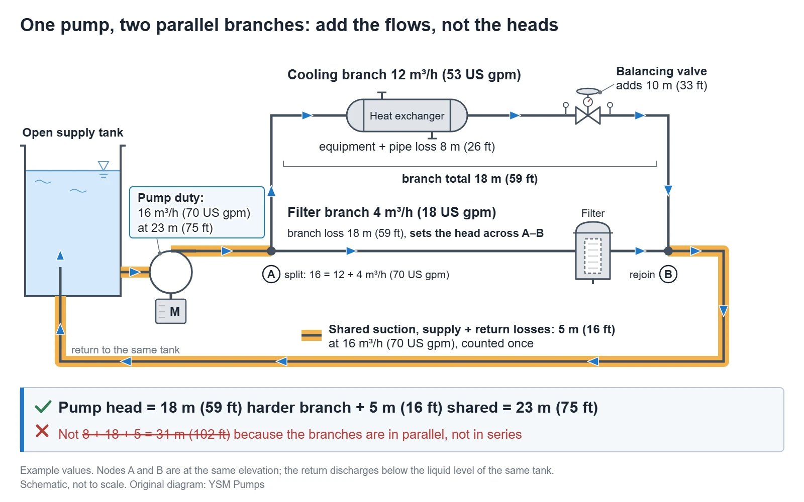
Short answer: when one pump feeds two branches that split and rejoin, it must deliver the sum of the branch flows, but only the head of the harder branch (the one needing more head at its design flow) plus the shared piping losses and any static head, counted once (Bulu, ‘Parallel Pipes’; Xylem, TEH-908A, pp. 8, 13 and 17). For example, a 12 m³/h (53 US gpm) cooling branch needing 8 m (26 ft) and a 4 m³/h (18 US gpm) filter branch needing 18 m (59 ft), with 5 m (16 ft) of shared losses, need 16 m³/h (70 US gpm) at 23 m (75 ft), not the 31 m (102 ft) you get by adding every pressure drop. The easier branch then needs a balancing valve to absorb the difference.
How to size a pump for two loads: draw the flow paths first
For a single load, see pipe friction and total system head. For two parallel loads, first sketch the real flow route:
- Source. Mark the tank, its normal and lowest levels, and the pump.
- Split and rejoin. Show where the flow divides and meets again.
- Total-flow equipment. Mark everything that carries the full flow; its loss counts once.
- Return levels. A branch returning to a different level has its own static difference.
- Operating cases. List start-up, filter cleaning or backwash, branch shutdowns and valve positions separately.
Get the right numbers from each equipment supplier
Ask the heat exchanger and filter suppliers for:
| Ask for | Why it matters |
|---|---|
| Minimum, normal and maximum flow for each branch | Sets what each branch must receive |
| Pressure drop versus flow for each item, clean and fouled | Gives the head each branch needs |
| Filter pressure drop just before cleaning, and the cleaning sequence | Size for that value, not a clean element |
| Filter feed, filtrate and any reject flow | Shows the real flow balance |
| Maximum allowable pressure of each item | A limit to check, not a loss to add |
Convert pressure drop to head with h = Δp/(ρg); for water, 1 bar (14.5 psi) is about 10.2 m (33.5 ft).
For a membrane filter, the branch loss includes transmembrane pressure (TMP), the pressure difference between the feed and filtrate sides. Fouling raises TMP at constant flow until backwash or chemical cleaning, so the branch loss grows between cleanings. DuPont’s IntegraTec ultrafiltration manual calls for clean-in-place when, among other triggers, operating TMP reaches its 2.1 bar (30.5 psi) maximum, about 21.4 m (70 ft) of water. Colder water needs a higher TMP for the same flow, so use the supplier’s loss at the lowest feed temperature (DuPont IntegraTec manual, Rev 8, April 2026, Sections 3.4, 7.1, 8.3, 9.6.1 and 12.1). DuPont’s WAVE design software defaults the TMP rise between cleanings to zero and urges users to enter a value from data and experience (DuPont, Specifying the Filtration TMP Increase between Processes for UF).
A pressure rating is a limit, not a loss the pump must supply. Check it the other way round: shut-off head plus suction pressure must stay below the lowest rating in the loop, such as IntegraTec’s 6.25 bar (90.65 psi) maximum inlet feed pressure at 20 °C (68 °F) (DuPont, Table 1).
Worked example: add the branch flows, size for the harder branch
The pump sizing values below are assumed for illustration, not measured or tested. Take an industrial cooling-water loop: an open tank feeds one centrifugal pump, and at a tee the flow splits into a cooling branch (heat exchanger) and a filter branch, which rejoin and return below the lowest liquid level of the same tank.
Where branches split and rejoin, the flow divides so that every branch has the same head loss between the junctions, and the branch flows add up to the main-line flow (Bulu, Sec. 3.4.2 ‘Parallel Pipes’, pp. 17–18). So the pump must supply the flow of all branches at the head of the harder branch plus the piping they share (Xylem, TEH-908A, December 2012, pp. 8, 15 and 17).
| Assumed input | Cooling branch | Filter branch | Shared suction, supply and return piping |
|---|---|---|---|
| Design flow | 12 m³/h (53 US gpm) | 4 m³/h (18 US gpm) | 16 m³/h (70 US gpm) |
| Loss at design flow | 8 m (26 ft), exchanger and pipe | 18 m (59 ft), just before cleaning | 5 m (16 ft), counted once |
US values are rounded individually.
- Pump flow: 12 + 4 = 16 m³/h (70 US gpm).
- Branch head: the filter branch needs 18 m (59 ft) between split and rejoin, so both branches get that head.
- Pump head: 18 + 5 = 23 m (75 ft), shared losses taken once, at full flow.
- Balancing valve: the cooling branch loses only 8 m (26 ft), so its valve must add 18 − 8 = 10 m (33 ft) at design flow.
Adding the cooling-branch, filter-branch and shared losses, 8 + 18 + 5 = 31 m (102 ft), is wrong: the branches are in parallel, not in series. Water that passes through the heat exchanger never passes through the filter.
Supply and return share one liquid surface, so while the loop runs full, static head is zero and all 23 m (75 ft) is friction and equipment loss (Hydraulic Institute, System Curves). If any part of the loop sits above the tank level, check that its pressure stays above atmospheric in every case and that the pump can fill the loop at start-up.
Without the valve, the cooling branch would take more than its share: an unbalanced network sends too much water through the least restricted circuits (IMI Flow Design, Balancing Overview). The valve is set to the design flow at commissioning (Danfoss, Manual balancing valves).
What if the filter’s loss is higher? If it is 25 m (82 ft) rather than 18 m (59 ft) just before cleaning, at the same 4 m³/h (18 US gpm), the pump needs 25 + 5 = 30 m (98 ft) and the cooling valve must absorb 25 − 8 = 17 m (56 ft).
A fixed valve setting is right at only one filter state. A cleaner filter needs less than the 18 m (59 ft) available between the split and rejoin points to pass 4 m³/h (18 US gpm), so it takes more than that and leaves the cooling branch slightly under 12 m³/h (53 US gpm). Ultrafiltration systems are typically designed for constant flow (DuPont, Section 5.1), so give such a filter its own flow control and set the cooling valve with the filter at design flow.
Build the loop’s system curve in two steps. At each head across the split and rejoin points, add the branch flows, with the valve at its set position. Then add the shared loss, and any static head, at that total flow. The pump runs where its curve crosses this system curve, and that point moves whenever the system curve changes (KSB, Operating point).
If the selected pump gives more than 23 m (75 ft) at 16 m³/h (70 US gpm), every branch without its own flow control runs above design flow (Xylem, TEH-908A, pp. 24–25). The branch balancing valve cannot fix that; closing it only pushes more water through the filter branch, unless that branch has its own flow control. Remove the excess with impeller trim or a speed change, keeping the point in an acceptable part of the curve (pump curves, system curves and BEP).
When one pump should not serve both branches
Head burned in a balancing valve is head the pump must still produce. In the worked example, the valve takes about a third of the pump’s 1.0 kW (1.3 hp) hydraulic power.
| Situation | Arrangement to assess first | Main trade-off |
|---|---|---|
| Similar branch heads, both run together | One pump, balancing valve on the easier branch | Fewer pumps; branch interaction still needs checking |
| One branch needs much more head | Separate circuit, or a booster on that branch | Less head burned in valves; recheck both branch flows |
| Filter often isolated for cleaning | One pump with a cooling-branch flow limit, or separate circuits | Cooling flow rises while the filter is out |
| Branch demands change often and unequally | Speed control plus branch flow control | One fixed valve setting cannot cover every case |
Check every operating case before ordering
Check at least these cases:
- both branches running, with the filter clean and just before cleaning;
- one branch isolated;
- filter backwash or cleaning, which may isolate the filter or draw extra flow from this pump;
- the highest-flow case, such as the balancing valve wide open before commissioning, or a clean filter;
- start-up and first fill;
- the lowest tank level and the highest tank temperature.
Isolating a branch removes a flow path. It follows from the parallel-path rule and the operating-point principle that the system curve becomes steeper, so a fixed-speed pump moves back along its curve toward lower flow and higher head, and the open branch receives more than its design flow unless it has its own flow control. Check that flow against the equipment maker’s maximum, and the discharge pressure against each item’s allowable pressure.
Internal recirculation tends to occur at low flow, such as when only the filter branch is open, which is why manufacturers list minimum flow rates (DOE/HI, Improving Pumping System Performance, May 2006, pp. 8 and 15). Check every case against the allowable operating region, which HI says the pump manufacturer should define. HI also warns that running at shut-off for more than a few seconds can cause serious mechanical problems, and that runout can cause cavitation, vibration and, in some pumps, driver overload (Hydraulic Institute, Pump Curves). So check motor power at the highest-flow case.
If both branches can close at once, provide minimum-flow protection designed for the application, such as a rated bypass or a low-flow trip (see system curve, BEP and low-flow operation).
While the return outlet stays below the lowest tank level, tank level does not change the head. But a lower level, a higher flow and warmer water all cut the net positive suction head (NPSH) margin, and here the cooling branch returns warmed water to the pump’s own tank. Check NPSH and cavitation for the worst combination, including backwash.
Record branch flows, not just total flow: a good total can hide an under-supplied branch.
Where YSM fits
We can review whether one end-suction process pump covers every operating case you list, against a reviewed curve for the size, and flag any case it cannot cover. The review is not a substitute for the equipment suppliers’ limits.
Send the flow-path sketch through the RFQ form in our ANSI process pump selection guide, which takes a drawing upload, with each branch’s design, minimum and maximum flow, supplier pressure-drop data, which branches run together, the cleaning sequence, the liquid and its highest temperature, and the lowest tank level.
Sources and dates
- DuPont, DuPont IntegraTec Modules Process and Design Manual, Form No. 45-D00874-en, Rev 8, April 2026
- DuPont, Specifying the Filtration TMP Increase between Processes for UF, WAVE help
- Bulu, A., Chapter 3: Local Energy (Head) Losses, Hydraulics lecture notes, Istanbul Technical University, accessed 26 September 2026
- Xylem (Bell & Gossett), TEH-908A Hydronic System Design with the Bell & Gossett System Syzer, December 2012
- IMI Flow Design, Balancing Overview, accessed 26 September 2026
- Danfoss, Manual balancing valves for hydronic balancing, accessed 26 September 2026
- Hydraulic Institute, System Curves, HI Data Tool, last updated 19 July 2024
- KSB, Operating point, Centrifugal Pump Lexicon, accessed 26 September 2026
- U.S. DOE and Hydraulic Institute, Improving Pumping System Performance: A Sourcebook for Industry, second edition, May 2006
- Hydraulic Institute, Pump Curves, HI Data Tool, last updated 19 July 2024