
Pump engineering — speed, impeller trim and the operating point
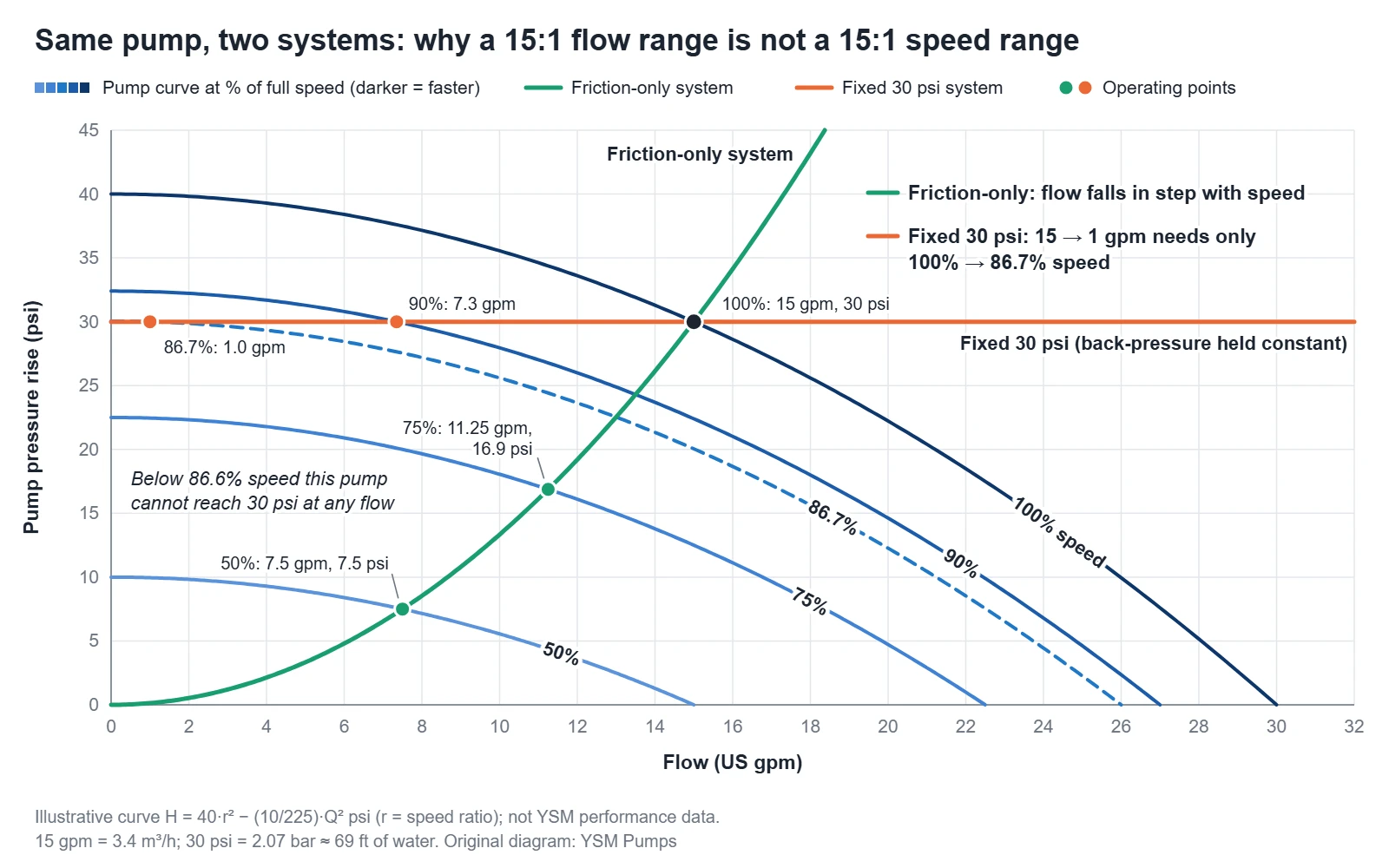
The pump affinity laws say that for the same pump, at corresponding points, flow changes in proportion to speed, head with the square of speed, and power with the cube of speed. They predict how the pump curve moves, not where the pump will run: the operating point still sits where the new curve crosses the system curve (HI, Pump Curves, 2024; KSB, Operating point). When a system needs a fixed pressure, as some test rigs do, head falls with the square of speed, so a 15:1 flow range cannot come from a 15:1 speed range. A pump with a 40 psi (2.76 bar) shutoff that must hold 30 psi (2.07 bar) covers a 15:1 flow range with only about a 13% speed change, and ends almost at shutoff (zero flow).
On this page: Pump affinity law formulas for speed and impeller diameter · What the affinity laws do not tell you · Worked example · Impeller trimming · Limits of the affinity laws · Controlling flow over a wide range · Where YSM fits
Pump affinity law formulas for speed and impeller diameter
Corresponding points are matching points on the old and new curves; for a speed change they lie on a parabola through zero flow and zero head (KSB, Pump affinity laws).
| Change | Flow | Head | Shaft power | Holds when |
|---|---|---|---|---|
| Speed, same impeller | Q₂/Q₁ = N₂/N₁ | H₂/H₁ = (N₂/N₁)² | P₂/P₁ = (N₂/N₁)³ | Corresponding points; efficiency assumed unchanged |
| Impeller diameter, same speed | Q₂/Q₁ ≈ D₂/D₁ | H₂/H₁ ≈ (D₂/D₁)² | P₂/P₁ ≈ (D₂/D₁)³ | Limited trims; approximate only |
The diameter row covers trimming one impeller at constant speed, not the model laws for geometrically similar pumps of different sizes (KSB, Affinity laws). The Hydraulic Institute (HI) assumes efficiency stays the same and refers to ANSI/HI 14.3 for the limits (HI, Pump Curves, 2024). KSB adds that the laws strictly hold only for frictionless, incompressible, non-cavitating flow, so constant efficiency is an approximation (KSB, Pump affinity laws).
A 10% cut in pump speed (N₂/N₁ = 0.9) gives, at corresponding points, 10% less flow (0.9), 19% less head (0.9² = 0.81) and about 27% less shaft power (0.9³ = 0.729). A friction-only system runs at roughly those points; a system with static head or a fixed pressure does not. Upward, 10% over speed adds about 21% to head, shutoff head included, and 33% to shaft power (1.1² = 1.21; 1.1³ = 1.331), so check the pump’s speed and pressure limits and the motor first. HI lists over speed, with resonance and minimum speed, among the mechanical design issues of variable speed (HI, Pump FAQs).
The diameter relations are weaker. The U.S. DOE/HI Sourcebook says they are not strictly accurate because of nonlinearities in flow and should be used as an approximation for small changes (DOE/HI, 2006, pp. 49–50). KSB’s trim rule differs: flow and head both scale approximately with the diameter ratio squared, while the vanes still overlap (KSB, Impeller trimming). For a 10% trim, both rules cut head by 19% at the mapped point, but flow by 10% (HI/DOE) or 19% (KSB). Neither replaces the manufacturer’s curve for the trimmed diameter, and the result depends on the system curve (DOE/HI, 2006, p. 50).
What the affinity laws do not tell you—where the pump will run
With the system unchanged, the operating point slides along the system curve to where the new pump curve crosses it (KSB, Operating point; see pump curves and system curves). Total system head is the sum of static head, friction head and any pressure difference between the suction and discharge ends; friction head rises roughly with the square of flow (pipe friction and total system head).
- Friction only. The system curve is close to a corresponding-point parabola, so flow falls roughly in step with speed and the best efficiency point (BEP) can move along the system curve (KSB, Closed-loop control).
- Static head or a fixed pressure. The system curve does not pass through the origin (KSB, System characteristic curve), so a slowed pump crosses it at a lower flow than the speed ratio predicts. DOE says the affinity laws do not give accurate results for systems with static head; draw the system curve to find the new duty points (DOE Tip Sheet #11, 2007).
Worked example—15 to 1 gpm (3.4 to 0.23 m³/h) at a fixed 30 psi (2.07 bar)
A test rig must hold a 30 psi (2.07 bar) pressure rise across the pump, about 69 ft (21 m) of water. Flow is stepped from 15 US gpm (3.4 m³/h) down to 1 gpm (0.23 m³/h). Suction is at 0 psig, so the held back-pressure equals the pressure rise. All values here are assumed for illustration, not YSM performance data. The pump curve is H = 40·r² − (10/225)·Q², with H in psi, Q in US gpm and r the speed ratio. At full speed it gives 40 psi (2.76 bar) at shutoff and 30 psi at 15 gpm. Two systems pass through that point: friction only (head rising with flow squared) and a fixed 30 psi.
| Speed | Friction-only system | Fixed 30 psi (2.07 bar) system |
|---|---|---|
| 100% | 15 gpm (3.4 m³/h) at 30 psi (2.07 bar) | 15 gpm (3.4 m³/h) |
| 90% | 13.5 gpm (3.07 m³/h) at 24.3 psi (1.68 bar) | 7.3 gpm (1.67 m³/h) |
| 86.7% (r = 13/15) | 13.0 gpm (2.95 m³/h) at 22.5 psi (1.55 bar) | 1.0 gpm (0.23 m³/h) |
| 86.6% (r = √0.75) | — | 0 gpm: shutoff equals 30 psi |
| 75% | 11.25 gpm (2.56 m³/h) at 16.9 psi (1.16 bar) | Cannot reach 30 psi |
| 50% | 7.5 gpm (1.70 m³/h) at 7.5 psi (0.52 bar) | Cannot reach 30 psi |
With friction only, the laws give the operating points directly: half speed, half the flow, a quarter of the pressure. The same 10% speed cut costs the friction-only system 10% of its flow and the fixed-pressure system about 51%.
For a curve that rises continuously to shutoff, as this one does, the lowest speed that can deliver any flow against a fixed pressure or static head is N_min/N = √(H_fixed/H_shutoff). Here √(30/40) = 0.866, so below 86.6% speed this pump cannot reach 30 psi. On a drooping curve, the peak head sets the limit instead. At 86.7% speed, shutoff is 30.04 psi (2.07 bar): a back-pressure rise of about 0.044 psi (0.003 bar), or a speed drop of under 0.1 percentage point, stops flow.
For an illustrative pump with a 40 psi (2.76 bar) shutoff, holding 30 psi (2.07 bar) means a 15:1 flow range (15 to 1 gpm, 3.4 to 0.23 m³/h) needs only a 13% speed change, from 100% to 86.7% speed, and leaves the pump almost at shutoff.
Near shutoff this curve is almost flat, and DOE/HI note that on a flat curve a small change in backpressure causes a large change in flow. Curves that droop at low flow, mainly on pumps with low specific speeds (an impeller index computed from speed, flow and head), can cross the system curve at more than one point, and the pump may “hunt” (DOE/HI, 2006, p. 15). KSB links unstable H/Q curves to undefined operating points and vibration (KSB, Operating behaviour).
The 1 gpm point is therefore arithmetic, not a recommended duty; the pump’s low-flow limits govern there. The realistic options are a bypass or minimum-flow arrangement, a smaller pump for the low range, or a positive-displacement pump.
Impeller trimming—how pumps are fitted to a duty
Pump casings and shafts are designed to take a range of impeller sizes, and manufacturers provide curves showing performance with different impeller diameters or trims (DOE Tip Sheet #7, 2006). Trimming machines the impeller’s outside diameter to match the operating point to the duty, permanently reducing flow and head without changing speed. KSB says low-specific-speed impellers (up to about n_s = 25 rpm on its metric scale) can be trimmed considerably with little loss of efficiency, while higher-specific-speed impellers lose efficiency noticeably (KSB, Impeller trimming). NPSH required (NPSHR) at a given flow is normally higher with a smaller impeller, so check it against the manufacturer’s data; manufacturers can often supply trim-correction charts (DOE Tip Sheet #7, 2006).
On an ANSI process pump, the nameplate impeller diameter, where shown, records the trim fitted at shipment. The nameplate cannot confirm whether the impeller has been cut since, so the current trim is confirmed before a part is made (reading a pump nameplate).
Our parts tables for Goulds 3196 pattern parts and Durco Mark 3 pattern parts list impellers at standard diameter. We supply the non-OEM replacement impeller cut to the trim diameter marked on the impeller or nameplate, or we select the diameter from the duty point (flow and head) you send. Every impeller is dynamically balanced before shipment.
Limits of the affinity laws—where the estimates mislead
Static head or fixed pressure. With high static head, a slowed pump can run at or near shutoff head, with greater shaft deflection, vibration and bearing loads (DOE/HI, 2006, p. 53).
Large trims. The Sourcebook says trimming changes the pump’s efficiency and the nonlinear diameter laws complicate performance prediction, so impeller diameters are rarely reduced below 70% of their original size (DOE/HI, 2006, p. 50). DOE Tip Sheet #7 gives a different reference: limit trimming to about 75% of the pump’s maximum impeller diameter, because heavy trimming mismatches impeller and casing, increasing internal recirculation and lowering efficiency. Never trim below the minimum diameter on the manufacturer’s curve (DOE Tip Sheet #7, 2006).
Viscous liquids. The laws assume the same liquid, and published curves are normally for 68°F (20°C) water. Viscosity changes head, flow, efficiency, NPSHR and power, and HI refers to ANSI/HI 9.6.7 whenever viscosity differs from that water (HI, Pump Curves, 2024; HI, Pump FAQs). KSB gives about 20 cSt (20 mm²/s) as a general threshold for noticeable changes (KSB, Viscosity). Because the Reynolds number changes with speed, friction effects do not scale with the laws either (KSB, Pump affinity laws). Use corrected curves at each planned speed; see viscosity and slurry selection.
NPSH required. KSB lists speed among the factors that set the pressure drop at the impeller inlet and says converting NPSH between speeds is largely a matter of testing (KSB, NPSH). It also notes that a safety buffer on NPSH available is provided when speed is reduced (KSB, Closed-loop control). Treat any speed-corrected NPSHR as an estimate and ask for the manufacturer’s data at each planned speed. Do not count on the buffer near shutoff: HI says operation away from BEP, in the allowable region, needs a larger NPSH margin (HI, Reliability Basics, 2022). See NPSH and cavitation.
Low flow near shutoff. HI describes a preferred operating region (POR) around BEP and an allowable operating region (AOR) limited by cavitation, heating, vibration, shaft deflection and fatigue. ANSI/HI 9.6.3 defines the POR from the pump’s hydraulic design, and the manufacturer should be consulted to define the AOR, so take both from the manufacturer. The AOR is stated at rated speed, and a published minimum flow usually corresponds to rated speed, so confirm both at the reduced speed (HI, Pump Curves, 2024; HI, Reliability Basics, 2022; DOE/HI, 2006, p. 53). Running at shutoff for more than a few seconds can cause serious mechanical problems (HI, Pump Curves, 2024). In a high-head, high-power pump, running at the low-flow limit or against a closed valve puts the drive power into the liquid, and its temperature rises rapidly (KSB, Operating behaviour). There is no universal minimum flow. A VFD does not remove the need to review motor cooling, minimum speed, static head and the operating region; see selecting pumps for low flow and system curve, BEP and low-flow operation.
In a throttled, constant-speed test of a pump rated 50 m³/h (220 US gpm) at 32 m (105 ft) and 2,900 rpm, head rose with flow, a hydraulically unstable region, from about 3 to 20 m³/h (13–88 gpm, 6–40% of rated flow), and the peak and kurtosis vibration indicators rose at 10–18 m³/h (44–79 gpm) (Luo et al., 2020).
Controlling flow over a wide range—throttling, bypass, speed, two pumps or a PD pump
| Method | What changes | What to check |
|---|---|---|
| Discharge throttling | Point usually moves to lower flow and higher head | Point inside the allowable region; energy lost across the valve (KSB, Control by throttling) |
| Bypass or recirculation | Pump runs at a higher flow than the process uses (KSB, Bypass) | Return location and temperature rise; power and NPSHR at the higher flow; avoid runout, the maximum-flow end of the curve (HI, Pump Curves, 2024) |
| Variable-frequency drive (VFD) | Pump curve moves down and to the left (DOE/HI, 2006, p. 52) | Static head, minimum speed, over speed, resonance, curves at each speed (HI, Pump FAQs) |
| Separate low- and high-flow pumps | Each covers its own part of the range | Changeover, and each pump’s operating region |
| Positive-displacement (PD) pump on a VFD | Flow roughly proportional to speed, slip aside, so 15:1 flow needs about 15:1 speed; the system sets the pressure, so a back-pressure valve still holds 30 psi (2.07 bar) | Flow at the lowest speed; relief valve; slip (internal leakage back to suction), which viscosity affects (DOE/HI, 2006, pp. 4, 23, 41; HI, Pump FAQs); drive setup and motor cooling at low speed, as for any VFD (selecting pumps for low flow) |
Energy. Throttling and bypass usually waste the most energy (KSB, Control by throttling; DOE/HI, 2006, p. 51; see pump efficiency and cost of ownership). In static-head-dominated systems, though, DOE notes that a bypass could be more efficient than throttling or an adjustable-speed drive (DOE/HI, 2006, p. 8). The cube law gives shaft power at corresponding points only; DOE ties it to centrifugal applications with no static lift (DOE Tip Sheet #11, 2007), and power spent against static head varies linearly with flow (DOE/HI, 2006, p. 115). HI notes that variable-speed savings shrink as static head is added, and that a drive does not raise pump efficiency: its own losses lower wire-to-water efficiency (HI, Pump FAQs).
Bypass heat check. KSB gives preventing heat-up in the low-flow range as one reason for a bypass, which returns to suction through a short loop or via a cooler (KSB, Bypass). In a closed test circuit, heat from the pump and the throttling element builds up from cycle to cycle, so cooling may be needed (KSB, Internal efficiency). Check the return temperature where a loop returns straight to suction or to a small reservoir.
Where YSM fits
YSM Pumps builds ANSI end-suction process pumps and non-OEM replacement parts. For a selection review, send each duty point (flow and head) and the system: static head, any pressure held constant, the control method and any parallel operation; the ANSI process pump selection guide lists the full inputs. Often one pump can cover two duties by speed change or trim, provided both stay in an acceptable part of the curve; we confirm this against a reviewed curve for the size. An affinity-law estimate is not a substitute for that check.
For a replacement impeller, send the nameplate data, including the impeller diameter where shown, and say whether the installed impeller has been cut down. You can send your operating data for a reviewed selection.
Goulds and 3196 are trademarks of ITT Inc. or its subsidiaries; Durco and Mark 3 are trademarks of Flowserve Corporation or its subsidiaries. They are used here only to identify the pump pattern the parts are made to fit. YSM Pumps (Jinan Yingsiman Machinery Co., Ltd.) is an independent manufacturer and is not affiliated with, authorised by, sponsored by or endorsed by ITT Goulds Pumps or Flowserve. All parts referred to are non-OEM parts manufactured by YSM.
Sources and dates
- Hydraulic Institute (HI), Pump Curves, last updated 19 July 2024; Pump FAQs, entries dated 2016–2024; Reliability Basics: Understanding NPSH, POR, and AOR, 21 March 2022.
- U.S. DOE and HI, Improving Pumping System Performance: A Sourcebook for Industry, 2nd ed., May 2006 (printed page numbers).
- U.S. DOE Pumping Systems Tip Sheets: #7, Trim or Replace Impellers on Oversized Pumps, September 2006, and #11, Adjustable Speed Pumping Applications, January 2007.
- KSB, Centrifugal Pump Lexicon, undated, accessed 26 September 2026: Pump affinity laws, Affinity laws, Impeller trimming, Operating point, System characteristic curve, Operating behaviour, Closed-loop control, NPSH, Viscosity, Control by throttling, Bypass, Internal efficiency.
- Luo, Y., Han, Y., Yuan, S. and Yuan, J., Research on the Single-Value Indicators for Centrifugal Pump Based on Vibration Signals, Sensors 20(11), 3283, 9 June 2020, doi:10.3390/s20113283.
- YSM Pumps, Goulds 3196 and Durco Mark 3 pattern parts pages, the pump curves page and the nameplate guide, reviewed 26 September 2026.