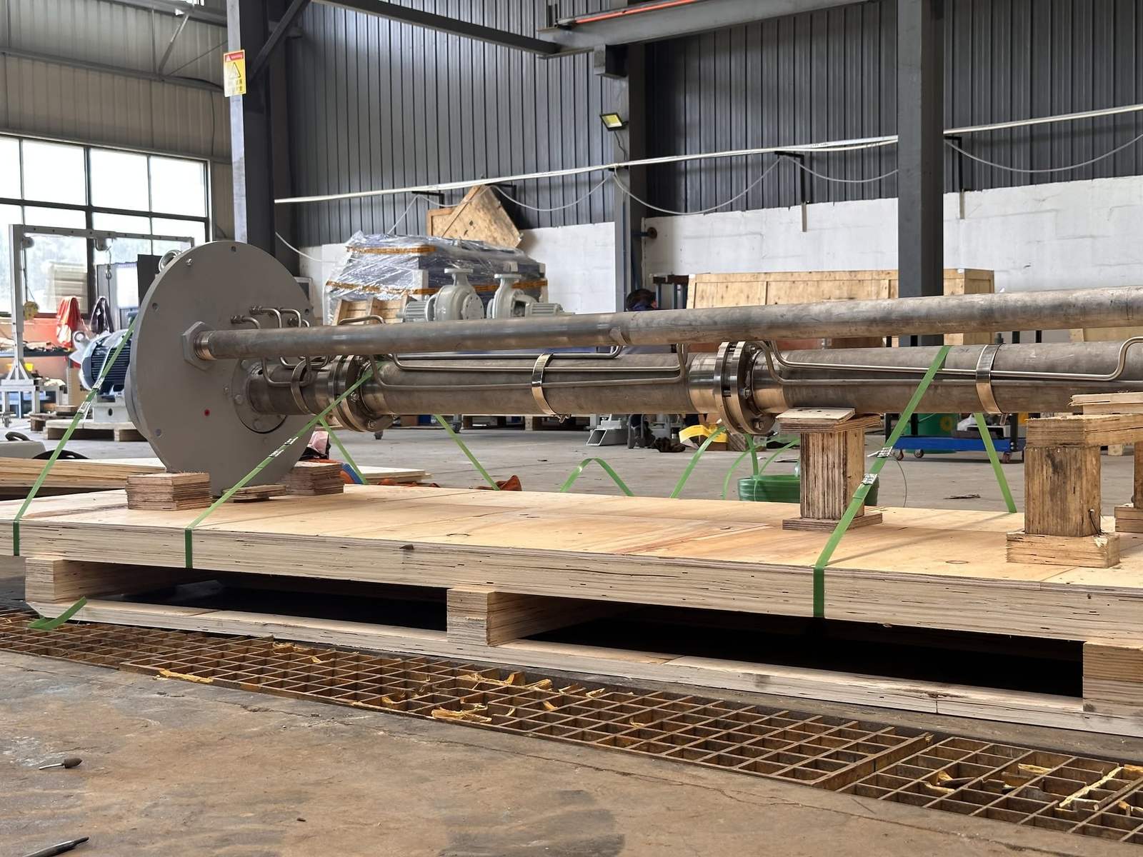
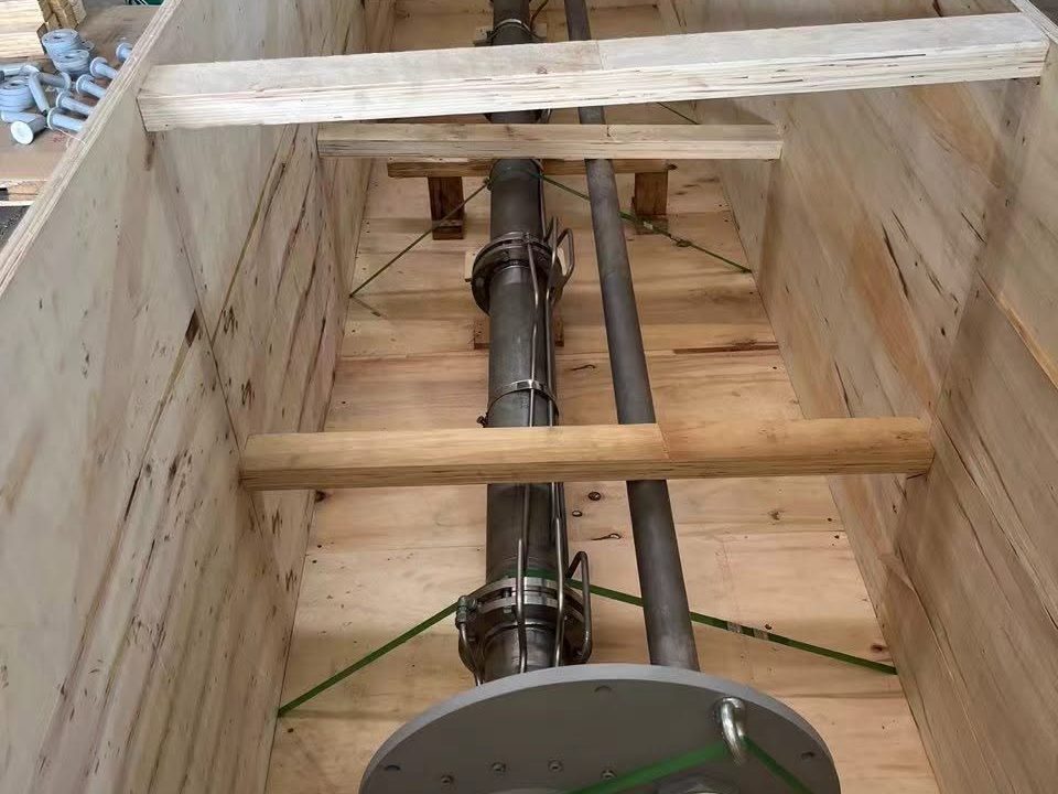
Vertical Sump & Process Pump · Goulds 3171 Pattern · Replacement Review
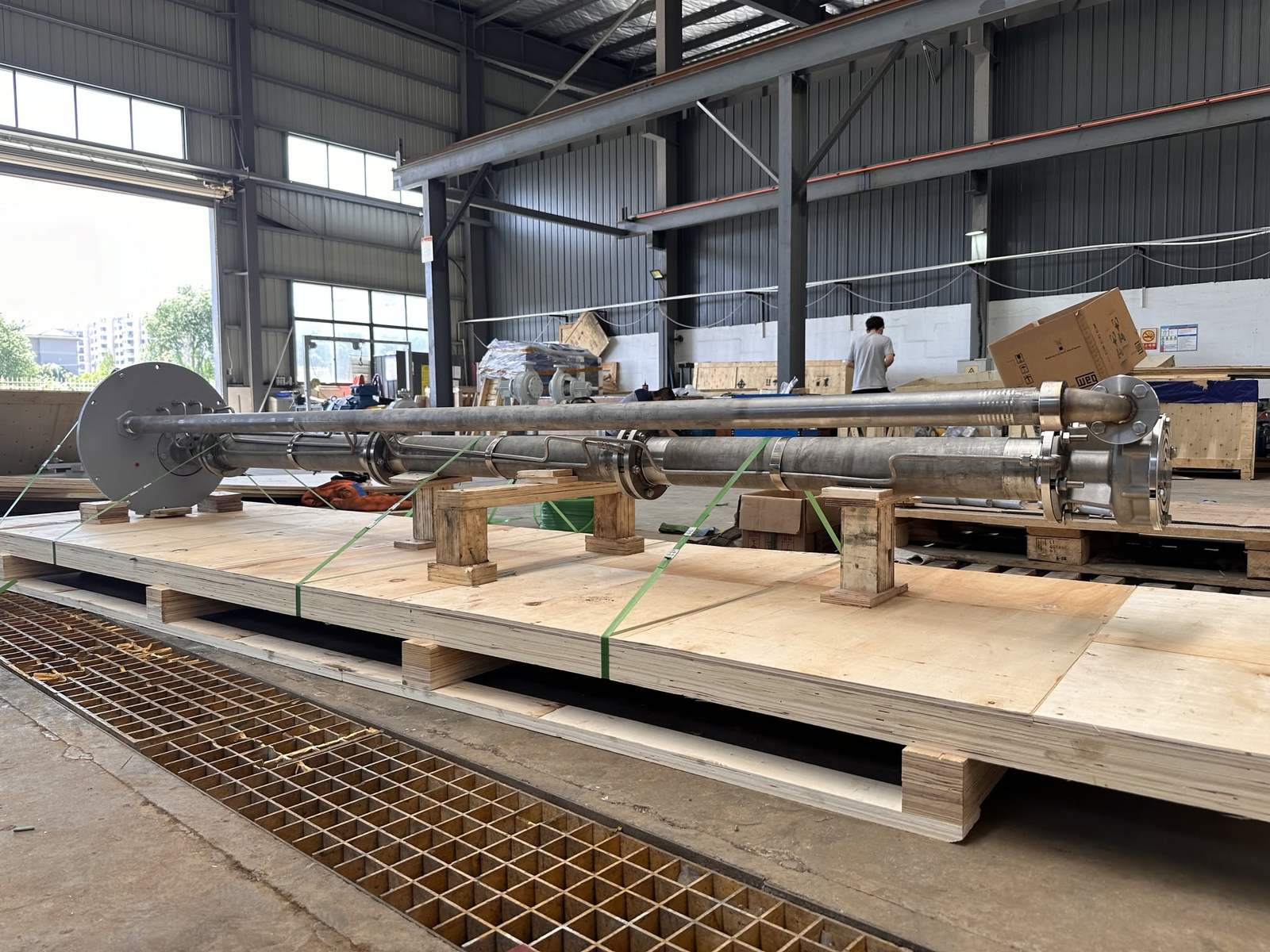
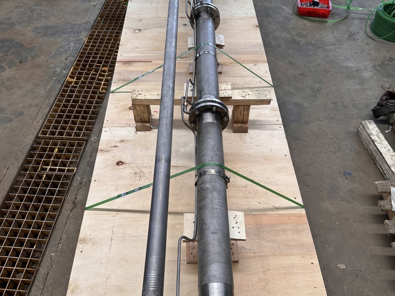
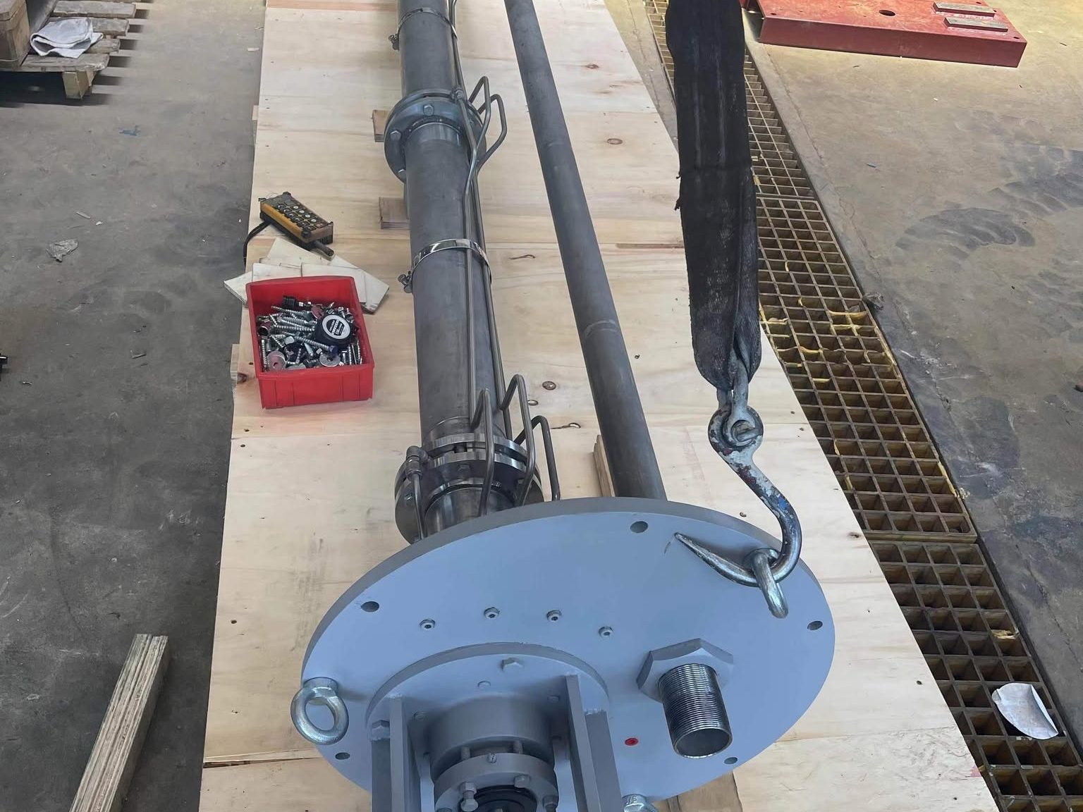
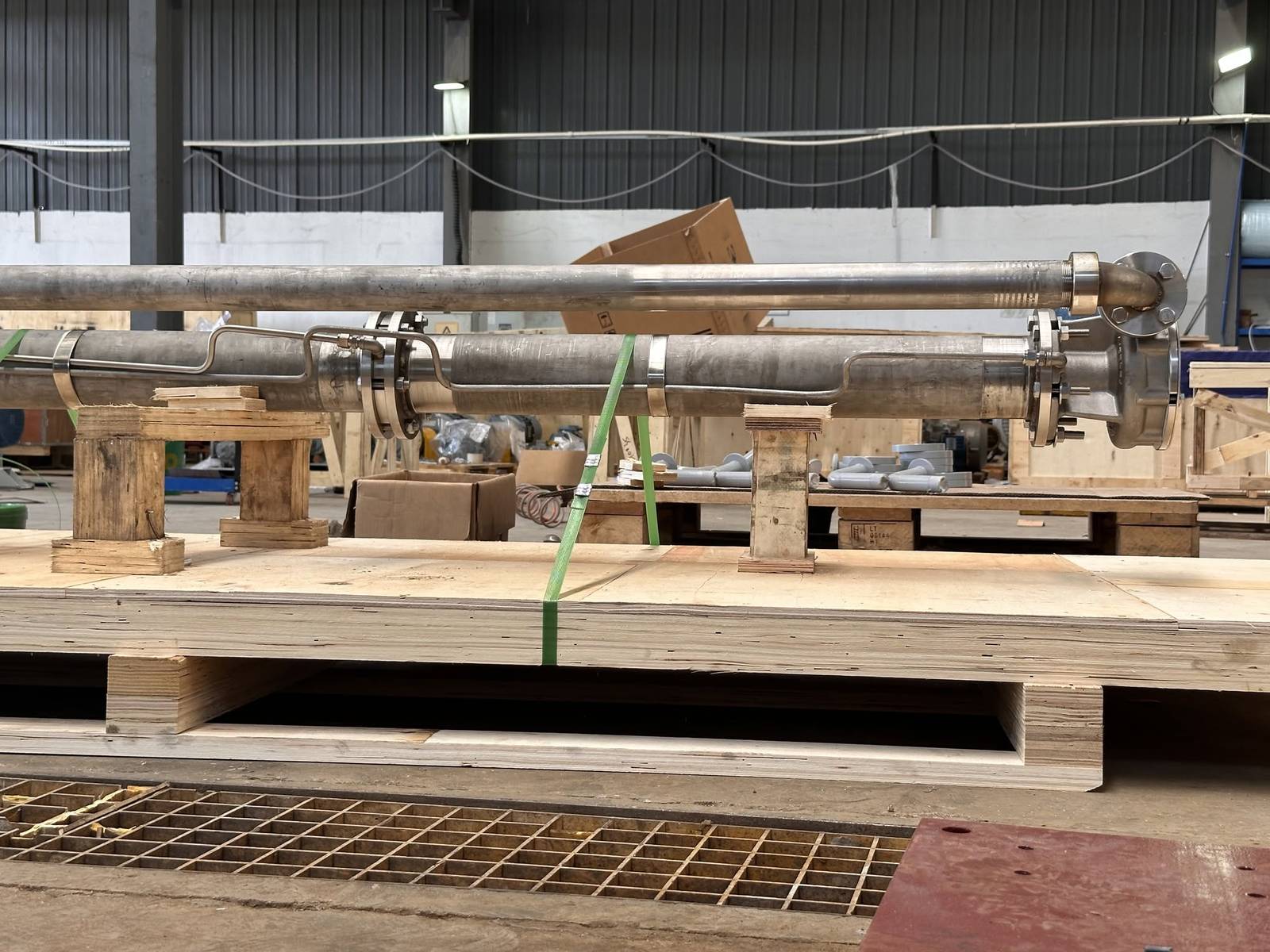
The G171 is YSM’s vertical submerged-bearing sump and process pump, built to the Goulds 3171 pattern for pits, sumps and tanks where the pump hangs from a support plate and the hydraulic end runs below the liquid surface. A 3171 replacement is never a flow-and-head exercise: the drawing-defined setting, the column and lineshaft arrangement, the number and spacing of steady bearings, the support plate and the discharge geometry decide whether the new pump drops into the existing pit without site rework. This page records the pattern’s reference envelope, the size and group references used for identification, and the data YSM reviews before quoting a complete pump, a pump-less-motor assembly or individual parts.
Reference maximums across the 3171-pattern size range; temperature to 450 °F (232 °C), construction and bearing material dependent. Head is confirmed on the size-specific curve, and setting is the drawing-defined dimension rather than nominal pit depth.
The 3171 Pattern in the YSM Programme
The 3171 pattern is a vertical sump and process pump with a fully open impeller, a tangential self-venting casing and a lineshaft carried in steady bearings inside the column. Drive units fall into S/ST, M/MT and L groups, and each group covers several hydraulic sizes. That is why “a 3171 shaft” or “a 3171 bearing” is not yet a specification: shaft diameter and length, column construction, bearing count and hydraulic size all change with the installed group and setting. The G171 reproduces the pattern’s installation and mechanical interfaces so that a confirmed size, group and setting can be replaced without field modification.
The standard 3171 is a vertical sump design and is not an ASME B73.1, ISO 2858 or API 610 pump. API 3171, CV 3171, LF 3171 and NM 3171 variants are reviewed separately against the installed pump data.
What is matched
Installation and mechanical interfaces
- Support plate outline, bolt pattern and pit-opening relationship
- Total setting, column sections and lineshaft lengths
- Steady-bearing count, spacing and housing registers
- Casing, impeller and suction-cover mating dimensions
- Discharge size, position and orientation relative to the plate
What is reviewed
Hydraulics, materials and driver
- Flow, head, speed and minimum liquid level against the selected size
- Wetted and bearing materials against the liquid, temperature and solids
- Motor frame, coupling and rotation when the driver is reused
- Documentation: GA drawing, nameplate, sectional drawing or part reference
Reference Envelope
| Parameter | 3171 pattern reference | Note |
|---|---|---|
| Capacity | To 3,180 US gpm (722 m³/h) | Reference maximum across the size range |
| Head | To 344 ft (105 m) | Confirmed on the size-specific curve |
| Temperature | To 450 °F (232 °C) | Construction and bearing material dependent |
| Setting (pit depth) | To 20 ft (6.1 m) | Drawing-defined setting, not nominal pit depth |
| Impeller | Fully open | Solids and fibre tolerance reviewed per duty |
| Casing | Tangential, self-venting | Vapour is released without an external vent |
| Lineshaft | Steady bearings in the column | Count and spacing set by setting, speed and shaft diameter |
| Drive-unit groups | S/ST, M/MT, L | Group read from the nameplate or drawing |
These values are the OEM reference envelope for the standard 3171 pattern. Final performance, speed, materials, setting and mechanical configuration are confirmed for the actual replacement pump.
Size and Group Coverage
OEM size references used for identification: 1×1-5, 1×1.5-6, 1.5×3-6, 1×1.5-8, 1.5×2-8, 2.5×3-8, 4×4-8, 1.5×2-11, 2.5×3-11, 3×4-11, 4×6-11H, 1.5×3-13, 2.5×3-13, 3×4-13, 4×6-13, 6×8-13 and 8×10-11, plus the LF low-flow variants shown in the OEM reference. A size code reads discharge × suction – nominal impeller diameter in inches.
| Buyer has | YSM verifies | Result |
|---|---|---|
| Model and size only | Group and hydraulic end | Configuration checklist to complete |
| Nameplate and setting | Shaft, column and steady bearings | Replacement scope |
| GA or dimensional drawing | Mounting and discharge interfaces | Dimensional match |
| OEM part number | Part identity and mating dimensions | Parts quotation |
Exact supply coverage and final configuration are confirmed during engineering review before quotation.
Four Interfaces Checked Before a Pump Is Built
Support plate and pit interface
Plate outline, bolt pattern, mounting position and the installed arrangement are checked against the existing pump so the new unit lands on the same opening.
Column, shaft and steady bearings
Setting, column sections, shaft section lengths and the steady-bearing arrangement are matched to the installed assembly rather than copied from another pump of similar depth.
Hydraulic end
Casing, impeller and suction-cover configuration and their critical mating dimensions are cross-referenced to the confirmed size and group.
Discharge interface
Discharge size, position, orientation and its relationship to the support plate are verified so that existing piping is reused without rework.
Setting Is Not Pit Depth
Two different dimensions
Pit depth is a civil dimension. Pump setting is a pump dimension measured between defined reference points on the supplier’s drawing — from the top of the support plate to the casing, suction cover or another stated datum. An unlabelled figure such as “3.5 m deep” cannot be converted into a shaft or column length.
What to record on site
Mark both endpoints of the setting on a field sketch, note whether plate thickness, gasket thickness or a mounting stand is included, and photograph the nameplate, support plate, pit opening, discharge elbow, column joints and any visible steady-bearing positions before dismantling.
Where the 3171 Pattern Runs
Industrial sumps and drainage
Process-area sumps, waste pits and plant drainage where the pump must sit in the liquid and be lifted out for service.
Tank unloading and pit transfer
Transfer from tanks and pits with variable liquid levels, where a flooded horizontal suction is not available.
Corrosive liquids
Acids, caustics and mixed process effluent; wetted and bearing materials are selected from the actual liquid chemistry, not the liquid name.
Hot service and molten sulfur
Application-specific construction review is required for high-temperature and molten-product duties before a configuration is offered.
Supply Scope
Complete pump
Hydraulic end, shaft and column system and support arrangement supplied together for full installed-pump replacement. Needs the confirmed model and size, setting and pit interface, and driver and speed data.
Pump less motor
Pump assembly below the driver interface for projects that retain a suitable motor. Needs the motor frame and mounting, coupling interface, and speed and rotation confirmation.
Replacement parts and assemblies
Casing, impeller and suction cover; shaft, column pipe, discharge pipe and steady-bearing components; selected support and mounting components. Quoted once part identity, mating dimensions, material and quantity are confirmed.
Reverse engineering
Worn or undocumented parts can be measured and re-drawn against the confirmed group and size; the resulting drawing is agreed before manufacture.
Materials, Bearings and Construction
Company-level capability
Wetted parts are cast and machined in-house from CF8M and CD4MCu through alloy 20, Hastelloy and titanium, with material certificates and spectrometer verification on request. Column and lineshaft components follow the same material logic as the hydraulic end.
Model-level confirmation
Steady-bearing material, lubrication method, sleeve material and any vapour-proof or high-temperature construction are confirmed per enquiry against the liquid, temperature, solids and the installed column arrangement.
Bearing quantity and spacing are never copied from another pump solely because the total setting is similar.
Data That Closes a 3171 Enquiry in One Cycle
Identification: model, size, serial number and drive-unit group if known. Duty: flow, head, speed, minimum and normal liquid level. Setting: the drawing-defined figure with both reference points. Shaft system: section lengths, diameters and couplings. Bearings: number, type, material and spacing. Installation: support-plate dimensions, pit opening, discharge size and orientation, removal clearance. Process: fluid, concentration, temperature, solids, vapour. Driver: motor power, speed, frame, coupling and rotation. Anything unknown can be marked as unknown.
3171 Replacement FAQ
What does “dimensionally interchangeable” mean for a 3171 replacement?
For a confirmed 3171 model, size, group and setting, the G171 is verified against the installation and mechanical interfaces required for the agreed scope: support plate, discharge, column, shaft, steady bearings and hydraulic end. It does not mean every 3171 variant is covered without review.
What is the fastest way to start a quotation?
Send the pump model and size together with a nameplate photo or the existing drawing. Setting and installation details can be added during engineering confirmation; a marked gap is reviewable, a silent one is not.
Can YSM quote only a shaft, a steady bearing or a hydraulic-end part?
Yes, once the exact part identity, mating dimensions, material and quantity are confirmed. For a shaft, record bearing journals, coupling or thread features, impeller attachment and every axial shoulder; for a bearing, the housing register, shaft diameter, bearing length and material.
Do I need flow and head for a direct replacement?
They are useful for hydraulic verification, but the installed model, size and drawing are the fastest starting point. Flow and head become essential when the duty has changed or when a different size is being considered.
Is the G171 an ANSI/ASME B73.1 pump?
No. The standard 3171 pattern is a vertical sump pump and is not defined by B73.1, ISO 2858 or API 610. The horizontal B73.1 families on this site are the G196 and D Mark III; API 3171 requirements are reviewed separately.
Which YSM family should I look at if the source is above ground or the suction can be flooded?
For a flooded horizontal suction the G196 or D Mark III pages apply; for a source below the pump where a horizontal, above-ground unit is preferred, the self-priming G3796 page applies.
What are the lead time and warranty for this pump?
Typical lead time is 4 weeks for a complete pump, 2 weeks for a bare wet end and 1 week for replacement parts, from deposit and approved drawings. Warranty is 12 months from shipment against defects in materials and workmanship within the reviewed duty. Late shipment attributable to YSM is compensated at 0.5% of contract value per week, capped at 5%.
What are the payment and delivery terms?
30% T/T deposit within 7 days of order, 70% T/T before shipment, or irrevocable L/C at sight; export-grade wooden-case packing; any Incoterms 2020 term (EXW Zibo, FOB Qingdao, CIF, DAP/DDP) as agreed in the quotation. Factory witness testing and third-party inspection (SGS, BV, TÜV) are accepted. Full terms: Commercial Terms
Goulds and 3171 are trademarks or product identifiers of ITT Goulds Pumps and are used solely for identification and replacement-reference purposes. YSM Pumps (Jinan Yingsiman Machinery Co., Ltd.) is an independent, non-OEM manufacturer and is not affiliated with, sponsored by or endorsed by ITT Goulds Pumps.
Request a 3171 Quote
A complete enquiry closes in one review cycle. Include the installed model and size, a nameplate photo, the drawing-defined setting with its reference points, the shaft and column arrangement, steady-bearing count and spacing, support-plate and pit-opening dimensions, discharge size and orientation, the liquid (composition, concentration, temperature, solids, vapour), driver data if the motor is reused, quantity, documentation needs, destination and target delivery date.
Anything unknown can be stated as unknown — a marked gap is reviewable, a silent one is not.
3171 Selection Decision Guide
Selection boundaries save both sides a review cycle: the fastest quotation starts on the right page. The G171 is the vertical sump answer inside YSM’s process-pump programme — crossing to another page is not a downgrade, it is a different answer to a different installation.
Start with the G171 when
- The pump hangs from a support plate into a pit, sump or tank and the hydraulic end runs submerged.
- An installed 3171-pattern pump needs a complete replacement, a pump-less-motor assembly, or shaft, column, bearing or hydraulic-end parts.
- The enquiry can describe, or can be helped to describe, the setting, column and steady-bearing arrangement.
Review another page when
- The suction can stay flooded and a horizontal ANSI/ASME B73.1 pump is installed: see the G196 or D Mark III pages.
- The source is below the pump but an above-ground horizontal unit is preferred: see the G3796 self-priming page.
- The installation is a deep well or a multi-stage vertical turbine duty: see the KVT page.