
Pump system head calculation guide
Does a Top Tank Inlet Increase Pump Head?
Reader question: “If the tank inlet is at the top .. this will increase the head right ?”
A top inlet adds head when it raises the free-discharge boundary. A submerged connection, pressurized tank and long friction-dominated line require a complete energy balance rather than a nozzle-height shortcut.
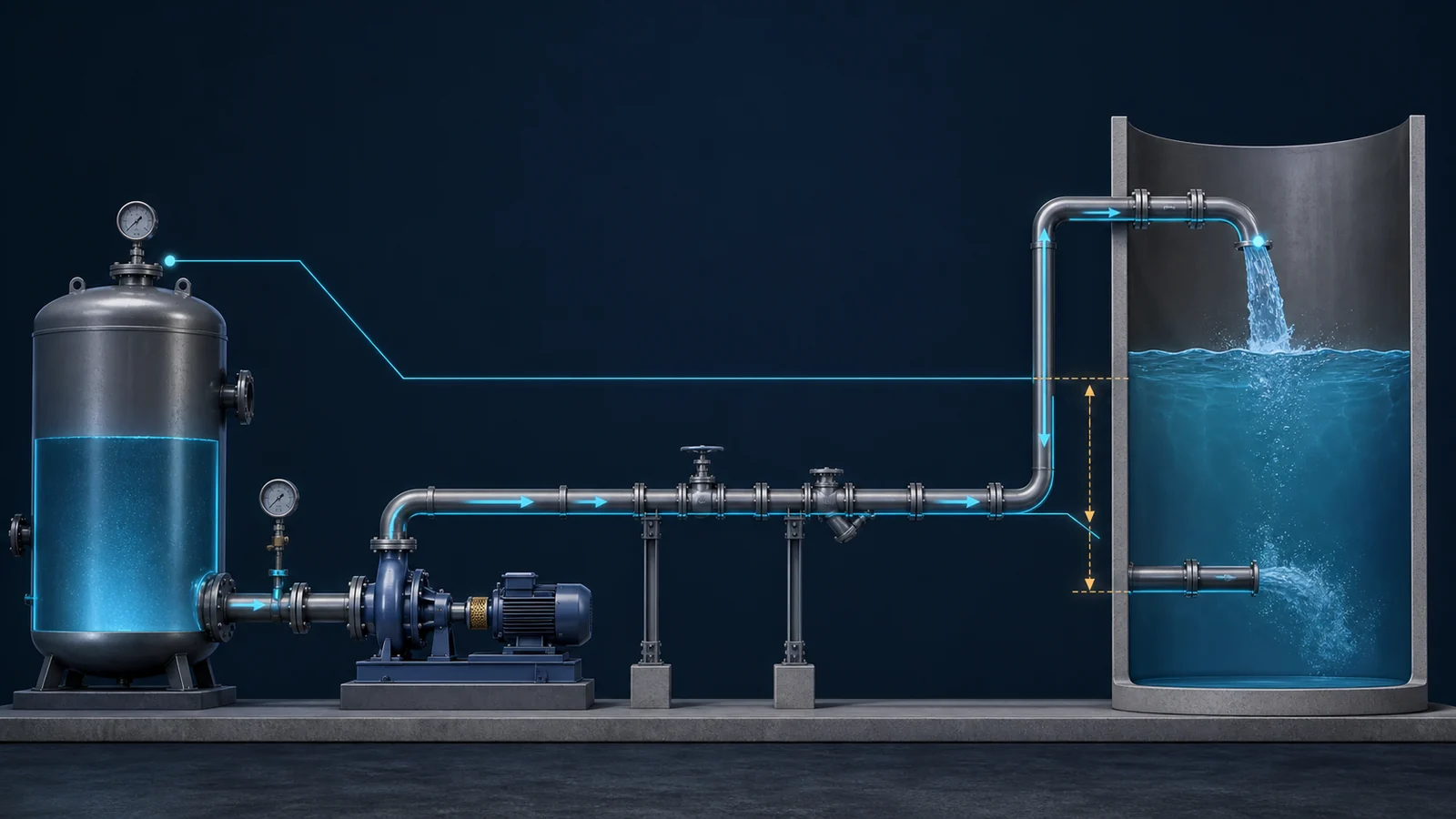
Four boundary cases
Nozzle elevation is only one part of total head
Use the actual energy boundary at the destination and include the complete pressure and friction terms.
Top free discharge
The open outlet elevation sets the destination boundary.
Submerged entry
Pressure head and elevation combine at the tank free surface.
Closed tank
Destination gas pressure adds to the required head.
Source pressure
Available flowing pressure can reduce added pump head.
Friction
Internal diameter, length, fittings and flow set the loss.
Envelope
Calculate minimum, normal and maximum system curves.
Short answer: yes, if moving the inlet to the top raises the point where the pipe freely discharges. But if both connections discharge into the same liquid-filled tank, moving the nozzle may not add the full nozzle-height difference. Tank pressure, liquid level and whether the outlet is submerged or open to atmosphere determine the answer.
The original Reddit discussion published on July 4, 2026 described approximately 400 metres of 4-inch pipe, a flow near 100 m³/h and source pressure around 3–3.5 kgf/cm².
A pump should not be selected from pipe length and discharge location alone. The complete system head must be calculated first.
The Total Head Equation
Hrequired = (z2 - z1) + (P2 - P1)/(ρg) + (v2² - v1²)/(2g) + hf + hm
This includes:
- Elevation difference
- Pressure difference between source and destination
- Velocity-head difference
- Straight-pipe friction
- Losses through valves, bends, entrances, exits and other fittings
The equation follows conservation of mechanical energy for fluid flow. See OpenStax, 2012.
The Answer Changes with the Tank Arrangement
| Tank arrangement | Useful destination boundary | Does the top inlet add head? |
|---|---|---|
| Top pipe ends above the liquid and discharges freely | Elevation of the open pipe outlet | Usually yes |
| Lower connection remains submerged in an open tank | Tank free-surface elevation | Not necessarily |
| Top and lower nozzles are both submerged | Tank free surface plus applicable losses | No simple nozzle-height addition |
| Closed or pressurized destination tank | Liquid level plus gas-space pressure | Pressure head must also be added |
Case 1: Free discharge above the liquid
If the top pipe ends above the maximum liquid level and discharges into air, the discharge boundary is the pipe outlet. Raising that outlet by 5 metres normally adds approximately 5 metres of static head, before accounting for added pipe and fittings. The exit velocity head may also be lost as the liquid leaves the pipe.
Case 2: Lower submerged connection to an open tank
At a submerged nozzle, pressure is higher because of the liquid above it, but the nozzle elevation is lower. When pressure and elevation head are combined correctly, the destination energy level is generally represented by the tank free surface.
Using the bottom-nozzle elevation while assuming atmospheric pressure at that submerged point would underestimate the required head.
Case 3: Top connection below the operating liquid level
If the top connection remains submerged during operation, the free surface is still the useful destination boundary. Moving the nozzle may alter pipe length and local losses, but it does not automatically add the full vertical distance between the nozzles.
Case 4: Closed or pressurized tank
For a pressurized destination, add the pressure-head difference:
Hpressure = (Ptank - Psource)/(ρg)
Gauge pressure cannot be converted to metres of liquid without considering density.
What the Source Pressure Contributes
A source pressure of 3–3.5 kgf/cm² is approximately 294–343 kPa. For water-like density, that corresponds to roughly 30–35 metres of pressure head.
If this pressure is available at the source while the system is flowing, it reduces the additional head the pump must supply. Verify:
- Whether the pressure is gauge or absolute
- Where it is measured
- Whether it remains available at 100 m³/h
- Its minimum and maximum values
- The actual liquid density
- Losses between the gauge and the proposed pump suction
If the system already delivers the required flow without a pump, the engineering question may be whether that flow remains reliable at minimum source pressure—not simply what pump should be installed.
Why the 400-Metre Pipe Cannot Be Ignored
Nominal pipe size is not the same as internal diameter. Schedule, lining, material and deposits can change the flow area.
For illustration only, suppose:
- Flow is 100 m³/h
- Actual internal diameter is exactly 101.6 mm
- Straight-pipe length is 400 m
- Darcy friction factor is 0.020
- Liquid properties are close to water
The velocity would be approximately 3.43 m/s. Using the Darcy–Weisbach equation:
hf = f(L/D)(v²/2g)
the straight-pipe loss would be approximately 47 metres, before adding bends, valves, entrances and exits.
This is not a final design value. The actual internal diameter, roughness, Reynolds number, liquid viscosity and fitting losses must be used. It demonstrates that friction in a long 4-inch line at 100 m³/h may matter more than a modest change in tank-inlet elevation.
The U.S. Army Corps of Engineers similarly defines total dynamic head as the sum of static lift, drawdown where applicable and friction losses. See USACE Water Supply Manual, April 2003.
Calculate the System Before Selecting the Pump
- Define the boundary points. Use source and destination free surfaces, verified pressure points or the actual free-discharge outlet.
- Record the operating envelope. Include minimum and maximum tank levels, source pressure and required flow.
- Confirm the pipe system. Record internal diameter, roughness, elevation profile, valves, fittings, strainers and the proposed top-inlet route.
- Build multiple system curves. Calculate minimum, normal and maximum conditions rather than one average case.
- Overlay candidate pump curves. The operating point is established by the interaction between the pump and system curves.
- Check suction conditions. Confirm NPSH margin at maximum flow, maximum temperature and minimum source pressure or level.
- Verify the complete selection. Check BEP, POR/AOR, power, material, sealing, motor supply and control method.
The Hydraulic Institute shows that static head combines elevation and pressure differences, while friction head changes with flow. See the HI system-curve tutorial, accessed July 18, 2026.
Common Mistakes
- Adding only the vertical pipe height
- Treating a submerged lower nozzle as atmospheric
- Ignoring pressure already available from the source
- Using nominal pipe size as internal diameter
- Ignoring friction in 400 metres of pipe
- Calculating only one tank level or source pressure
- Selecting a pump from discharge pressure alone
- Assuming a pump delivers its advertised maximum flow in every system
- Converting pressure to metres without using liquid density
Where YSM Process Pumps Fit
If the liquid and service are suitable for an ANSI process pump, YSM can evaluate the G196 or D Mark III families after the system curves are established.
The RFQ should include minimum, normal and maximum flow, system-head calculations, source and destination pressures, tank-level range, pipe and fitting data, liquid properties, suction conditions, NPSHA and the required control method.
Sources and Dates
- Original Reddit discussion — July 4, 2026
- Hydraulic Institute system-curve tutorial — accessed July 18, 2026
- Hydraulic Institute combined pump and system curves — accessed July 18, 2026
- Hydraulic Institute Pump FAQs — system-curve section updated July 2025
- OpenStax Bernoulli equation — 2012
- USACE Water Supply Manual — April 2003
Related Technical Guides
System Curve, BEP and Low-Flow Operation
Understand why the pump does not set its operating flow independently of the system.
Read the operating-point guideSelection Data Beyond Flow and Head
Prepare the complete operating range, liquid, suction, control and document data.
Open the selection checklistNeed the System Curve Reviewed?
Send the piping layout, actual internal diameter, fitting list, elevation profile, source pressure range, destination-tank levels, required flow and liquid properties.