
How Accurate are the Head, Flow, and BHP values on a Pump Nameplate?
Pump nameplate values identify stated conditions; they do not, by themselves, establish the flow, head or shaft power of the installed pump today. Judge factory performance against the agreed test standard, acceptance grade and supplied configuration. Judge site performance using measured flow, total differential head, actual speed and an appropriate power measurement.
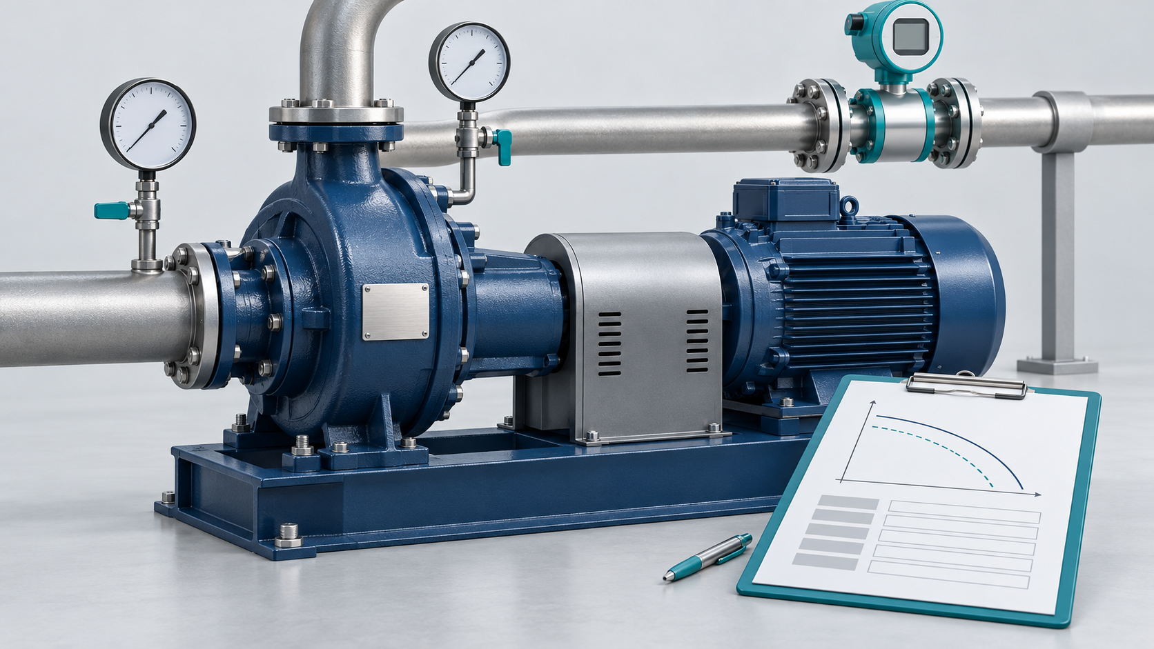
AI-generated concept illustration. The blank nameplate, instruments and unscaled curves are illustrative, not certified performance data, a YSM product photograph or an installation drawing.
There is no defensible universal percentage for “nameplate accuracy” without knowing what each field represents and how the pump was specified and tested. The Hydraulic Institute lists ANSI/HI 14.6:2022 for hydraulic performance acceptance testing; its published contents distinguish acceptance grades and tolerance fields. Hydraulic Institute, standards listing and 2022 test-standard contents, accessed November 1, 2026, 2022 contents PDF
First identify the plate and the meaning of its fields
The Reddit author is a maintenance engineer asking how a new pump’s specified performance relates to the pipe system. That is a different question from whether a manufacturer met a contractual factory guarantee. Original question, October 19, 2026
Photograph both the pump and motor identification plates. Ask the supplier to identify ambiguous fields rather than assuming every horsepower figure means the same thing.
| Item to identify | What to establish before comparing it with a site reading |
|---|---|
| Pump flow and head | The stated duty, speed, impeller diameter and test liquid |
| A BHP or pump-input-power entry | Whether it refers to required shaft power at a specified condition |
| Motor rated output | The motor rating, separately from the pump’s absorbed power |
| Electrical input measurement | Whether it includes the drive and motor losses |
| Serial number and configuration records | Whether the curve belongs to the assembly currently installed |
This is a document-review checklist. Exact plate conventions vary; obtain the manufacturer’s explanation where the record is unclear.
Compare the right levels of performance evidence
The Hydraulic Institute distinguishes family selection charts, published curves and certified curves. A certified curve relates to the particular pump and impeller trim purchased and may identify the test standard and acceptance grade. Hydraulic Institute, Pump FAQs, March 2018 entry, accessed November 1, 2026
| Evidence | Appropriate use | Remaining question |
|---|---|---|
| Identification plate and datasheet | Establish what was specified or supplied | What does each stated value represent? |
| Published performance curve | Compare expected behaviour across flow | Does speed, trim and liquid match the installation? |
| Serial-specific test documentation | Evaluate the tested pump against agreed acceptance requirements | What tolerances and conditions were agreed? |
| Simultaneous site measurements | Establish the installed operating condition | Are the instruments and measurement corrections adequate? |
Keep manufacturing tolerance, measurement uncertainty and a changed operating point separate in the investigation. A site reading different from the nameplate is a reason to examine the records and conditions; it does not alone prove a defective pump.
Why a new pump can run away from the stated point
The operating point is determined jointly by the pump and system characteristics. Valves, equipment losses and liquid levels can therefore alter the installed flow and head. DOE’s sourcebook treats the complete system and warns against evaluating a pump as an isolated component. DOE/HI, Improving Pumping System Performance, May 2006
For this investigation, document the current valve positions, tank levels and operating equipment. Then compare actual speed and installed impeller information with the curve. DOE specifically advises measuring actual speed when using performance curves. A clean factory test and a changed installation answer different performance questions. DOE/HI, May 2006
Measure total differential head, not discharge pressure alone
For steady incompressible flow between the chosen suction and discharge measurement sections, total pump head is:
H = (pᵈ − pˢ)/(ρg) + (vᵈ² − vˢ²)/(2g) + (zᵈ − zˢ)
Here p is pressure, ρ is liquid density, v is mean velocity, and z is elevation. Use consistent units and pressure references. Include the velocity and elevation terms where relevant; measurements taken remotely from the pump may also require intervening-loss corrections. The Hydraulic Institute defines pump head as the increase in total head from suction to discharge. Hydraulic Institute, Pump Curves, accessed November 1, 2026
Illustrative calculation, not field data: assume water density 1,000 kg/m³, g = 9.81 m/s², equal measurement elevations and equal velocities. If discharge pressure is 300 kPa gauge and suction pressure is 100 kPa gauge, head is approximately 20.4 m. If suction pressure instead falls to zero gauge while discharge remains 300 kPa gauge, head is approximately 30.6 m.
The unchanged discharge reading conceals a substantially different differential head. This example does not predict the accompanying flow; that needs measurement and comparison with the appropriate curve.
Distinguish pump BHP from electrical power
The pump’s absorbed shaft power and the electrical input to its motor are different quantities. The Hydraulic Institute’s pump-power relationship connects hydraulic power with pump efficiency, while its field-measurement guidance also considers motor input and losses. Hydraulic Institute, Pump Curves, Pump FAQs, field power measurement guidance, accessed November 1, 2026.
Second illustrative calculation: at 50 m³/h and 30 m head with the same assumed water density, hydraulic output is approximately 4.09 kW, using ρgQH. At an assumed pump efficiency of 70%, shaft input is 5.84 kW. At an assumed motor efficiency of 90%, motor electrical input is 6.49 kW, excluding drive losses.
These efficiencies are assumptions, not measured product performance. The calculation shows why comparing a motor’s rated horsepower directly with a measured electrical input can lead to the wrong conclusion. For measured motor input, the Hydraulic Institute discusses voltage, current and power factor; current alone is insufficient for that calculation.
What experimental work says about checking operating conditions
A 2020 centrifugal-pump experiment by Luo and colleagues used simultaneous instrumentation for flow, inlet and outlet pressure, speed and vibration. The test pump was rated at 50 m³/h, 32 m head and 2,900 rpm. The study investigated changing flow and suction conditions and found vibration features useful for identifying off-design behaviour. Luo et al., June 9, 2020, Tables 1–2 and experimental procedures
The study supports evaluating operating conditions together. It does not measure nameplate accuracy or establish an acceptance tolerance for your pump. Its published measurements must not be substituted for the particular pump’s factory report.
A practical verification sequence
- Collect the pump and motor identification, current configuration and maintenance history.
- Obtain the matching curve, datasheet and available factory test documentation.
- Agree on measurement locations, instrument suitability and a stable operating condition.
- Measure flow, suction/discharge conditions, speed and power concurrently using qualified personnel.
- Calculate total head and compare with the correct curve, accounting for relevant liquid and configuration differences.
- If making a factory-performance claim, evaluate it against the documented acceptance agreement rather than an invented universal tolerance.
For a YSM enquiry involving Summit 2196 ANSI Pumps or the D Mark III series, send this evidence with the existing pump size and impeller details. It provides a useful basis for reviewing a proposed replacement or part. The Summit page describes a YSM non-OEM replacement offering; series identification alone does not prove hydraulic equivalence.
The useful answer to “how accurate?”
Pump nameplate accuracy must be evaluated against the meaning and conditions of the stated values. Use the matching test documentation for factory acceptance and measured total head, flow, speed and appropriate power data for the site comparison. That establishes whether the discrepancy concerns documentation, the operating condition or pump performance.
Sources and dates
- Reddit question, r/ChemicalEngineering: October 19, 2026, date from public search index; title and body directly read November 1, 2026.
- Hydraulic Institute pages linked above: accessed November 1, 2026. Standards listing identifies ANSI/HI 14.6:2022. Only the public contents were used; no numerical tolerance has been extracted from inaccessible standard text.
- DOE/HI sourcebook: second edition, May 2006.
- Luo et al.: Sensors 20(11), 3283, June 9, 2020; experimental PDF reviewed.
- YSM product destinations checked November 1, 2026.