
Pump basics — centrifugal pump parts, functions and materials
A centrifugal pump’s parts fall into three groups. The wet end moves the liquid: the casing, the impeller that spins inside it and the cover that closes the casing. The seal area stops the liquid escaping where the shaft leaves the casing: a mechanical seal or packing, usually running on a shaft sleeve. The power end carries the rotor and transmits the drive: the shaft, its bearings and the bearing frame. A coupling joins the pump to its motor on a common baseplate.
The diagram below labels the main parts of an end-suction process pump, the most common industrial layout. The sections that follow give what each part does, what it is usually made of and how it wears.
On this page: diagram · parts and functions table · wet end · seal area · power end · coupling and baseplate · back pull-out · wear and spare parts · FAQ
Centrifugal pump parts diagram
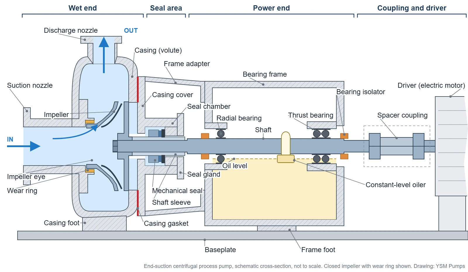
Follow the liquid through the drawing. It enters through the suction nozzle and reaches the eye of the impeller. The rotating vanes throw it outward, so it leaves the impeller fast and at higher pressure. The volute collects it all round the impeller, and its throat and the discharge nozzle slow it down, turning speed into further pressure, before it reaches the piping. Behind the impeller, the casing cover closes the casing and the shaft seal stops liquid leaking out along the shaft. The bearings in the frame hold the shaft in position against the hydraulic forces, and the coupling brings in the power from the motor.
Centrifugal pump parts and their functions
The table lists each part, the group it belongs to, what it does and what it is usually made of on an industrial process pump. The last column separates wear parts, which are renewed during the life of the pump, from structural parts, which normally last as long as the pump unless they are damaged.
| Part | Group | What it does | Typical materials or type | Wear or structural |
|---|---|---|---|---|
| Casing (volute) | Wet end | Holds the liquid under pressure, collects it from the impeller and turns its speed into pressure. | Cast or ductile iron in water and general service; carbon steel (WCB), stainless steel (CF8M), duplex (CD4MCu), nickel alloys or titanium in process service | Structural: the pressure boundary |
| Suction and discharge nozzles | Wet end | Connect the casing to the suction and discharge piping through flanges. | Cast with the casing | Structural |
| Impeller | Wet end | Rotates and adds energy to the liquid: its vanes throw the liquid outward from the eye. | Usually the casing material; bronze and cast iron in water service | Wear part |
| Wear rings | Wet end | On closed impellers, form a close running clearance that limits leakage from discharge back to suction. | Bronze or cast iron in water service; hardened 12% chromium steel, other stainless steels or composites in process service, paired to resist galling | Wear part |
| Casing gasket | Wet end | Seals the joint between the casing and the casing cover. | Compressed fibre, graphite, PTFE or spiral-wound | Renewed whenever the joint is opened |
| Casing cover (back plate) | Wet end | Closes the back of the casing; on end-suction process pumps it usually also forms the seal chamber or stuffing box. | Usually the casing material | Structural |
| Seal chamber or stuffing box | Seal area | The bore around the shaft that houses the shaft seal: a mechanical seal or rings of packing. | Usually part of the casing cover; cast in the casing on split case pumps | Structural |
| Mechanical seal | Seal area | Stops leakage along the shaft with two flat faces, one turning with the shaft and one held still. | Faces in carbon, silicon carbide or tungsten carbide; elastomer or PTFE secondary seals | Wear part |
| Packing and lantern ring | Seal area | On packed pumps, rings of braided packing throttle the leakage; a lantern ring, where fitted, feeds sealing water. | PTFE, graphite and aramid-based packing; lantern ring in PTFE or metal | Wear part |
| Seal gland | Seal area | Holds the stationary seal face in place, or compresses the packing. | Stainless steel or the wet-end alloy | Structural |
| Shaft sleeve | Seal area | A renewable wear surface under the seal or packing that protects the shaft. | Stainless steel or a higher alloy, hard-faced where packing runs on it | Wear part |
| Shaft | Power end | Carries the impeller and transmits torque from the driver. | Carbon or alloy steel such as SAE 4140, or stainless steel | Structural; replaced if bent or its fits are worn |
| Radial bearing | Power end | The inboard bearing, nearest the impeller: carries radial load only and lets the shaft float axially. | Single-row deep-groove ball bearing | Wear part |
| Thrust bearing | Power end | The outboard bearing: carries the axial thrust and part of the radial load, and fixes the shaft’s axial position. | Double-row angular-contact ball bearing, or a matched pair of angular-contact bearings | Wear part |
| Bearing frame and housing | Power end | Holds the bearings in line and carries the lubricating oil. | Cast iron or ductile iron | Structural |
| Bearing isolators or lip seals | Power end | Keep the oil in and water, dust and vapour out where the shaft leaves the frame. | Labyrinth isolators in bronze or stainless steel; elastomer lip seals | Lip seals wear; labyrinths have no rubbing contact |
| Oil and constant-level oiler | Power end | The oil lubricates and cools the bearings; the oiler tops the sump up to a set level. | Mineral or synthetic oil | Oil changed at intervals |
| Frame adapter | Power end | Joins the bearing frame to the casing and centres the rotor in the casing bore. | Ductile iron | Structural |
| Coupling | Coupling and driver | Transmits torque from the motor to the pump shaft and takes up small misalignment. | Steel hubs with an elastomer or steel-disc flexible element | The flexible element wears |
| Baseplate | Coupling and driver | Holds the pump and the motor in alignment on the foundation. | Fabricated steel, cast iron or polymer concrete, usually grouted to the foundation | Structural |
| Driver | Coupling and driver | Turns the pump: usually an electric motor, sometimes a steam turbine or an engine. | Bought in to suit the pump power and the site supply | — |
Materials are typical for process pumps; the right material for a given pump depends on the liquid, its concentration and temperature. Cast grades for the wet end are listed in the cast alloy reference.
The table describes an end-suction pump with its impeller overhung beyond the bearings. Other layouts use the same parts in different places. Between-bearings pumps, split case pumps among them, carry a bearing at each end of the shaft and so have two shaft seals. Close-coupled pumps mount the impeller on the motor shaft and have no bearing frame or coupling. Vertical pumps hang the wet end below the driver. The API 610 pump types guide sorts these layouts.
Wet end: casing, impeller, wear rings and cover
The wet end is every part the pumped liquid touches on its way through the pump. It sets the hydraulic performance, and its materials decide whether the pump survives the liquid.
Casing and volute
The casing is the pressure-containing shell around the impeller. On most single-stage pumps its passage is a volute: a spiral that starts close to the impeller at the cutwater and widens as it collects the liquid leaving the impeller all round its circumference. The throat of the volute and the tapered discharge nozzle then slow the liquid down and turn its speed into pressure. Larger pumps often use a double volute, two spirals opposite each other, which largely cancels the radial force on the impeller; axially split multistage pumps usually have double volutes too. Ring-section multistage pumps and vertical turbine bowls usually use a diffuser instead, a ring of fixed guide vanes around the impeller.
The suction and discharge nozzles are cast as part of the casing and end in flanges. An end-suction pump takes the liquid in along the shaft axis and usually discharges it upward from the top centreline; a split case pump has its casing divided along the shaft, with both nozzles in the lower half. Because the casing holds the full discharge pressure, it is hydrostatically tested before it is assembled, and it is replaced only when it is cracked, has lost wall thickness or its fits are damaged.
Impeller
The impeller is the part that does the work. Liquid enters at its centre, the eye, and the vanes accelerate it outward as the impeller turns. Most process pump impellers have backward-curved vanes. They come in three forms:
| Impeller type | Construction | Where it is used |
|---|---|---|
| Closed | Vanes between two shrouds: a front shroud around the eye and a back shroud on the hub side. Leakage at the eye is limited by a close clearance, usually wear rings. | Clean liquids; the most efficient form |
| Semi-open | A back shroud only; the open vane edges run close to a stationary face. | Liquids with some solids or fibre |
| Open | Vanes on a hub with little or no shroud. | General chemical duty, solids, stringy material and liquids that would clog a closed passage |
Many impellers also carry pump-out vanes on the back shroud, or balance holes used together with a back wear ring. Both lower the pressure behind the impeller and with it the axial thrust on the bearings; pump-out vanes also lower the pressure at the seal. On most ASME B73.1 pumps the impeller screws onto the end of the shaft; on others it is keyed and held by a nut. An O-ring or gasket at the impeller keeps the liquid off the shaft and is renewed at every overhaul. An impeller can also be trimmed to a smaller diameter to move a pump onto its duty point, so the trimmed diameter is recorded for each pump; the pump and system curves guide shows the effect.
Wear rings
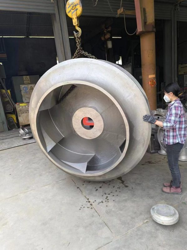
On a closed impeller, liquid at discharge pressure tries to leak back to the suction around the outside of the front shroud. Wear rings stop most of it: a stationary ring in the casing surrounds a close-fitting neck on the impeller, which sometimes carries a renewable impeller ring of its own. The clearance between them is small, so leakage is small. As the rings wear, the clearance opens, more liquid recirculates, and head and efficiency fall. Renewing the rings restores the clearance without replacing the casing; where the impeller has no ring of its own, its neck is machined true and a matching ring is fitted in the casing.
The two rings can touch if the rotor deflects, so they are made as a pair that resists galling: different materials, or hardenable materials at different hardness. Bronze and cast iron are usual in water service; hardened 12% chromium steel, other stainless steels and composite rings are used in process service. YSM’s S series split case pump, for example, lists casing wear rings in tin bronze, grey cast iron, silicon brass and stainless steel. YSM supplies wear rings as spares for its own pumps and as part of reverse engineered pump parts. Open and semi-open impellers, used in most ASME B73.1 chemical process pumps, have no wear rings: their clearance is at the vane edges and is set axially rather than by rings, and some designs add a renewable wear plate or suction-side liner facing the vanes.
Casing cover and casing gasket
The casing cover, also called the back plate, closes the back of the casing behind the impeller. On end-suction process pumps it usually also forms the seal chamber or the stuffing box, so it is both a pressure part and the housing of the shaft seal. The casing gasket seals the joint between casing and cover. A used gasket has taken a permanent set, so a new one is fitted every time the joint is opened.
Seal area: where the shaft leaves the casing
The shaft has to pass from the liquid-filled casing to the bearing frame. The seal area is where that happens, and shaft seal failure is the most common cause of process pump repairs.
Seal chamber or stuffing box
A stuffing box is a bore sized for rings of packing, often with a lantern ring part-way along it, and a gland at its outer end. A seal chamber is a bore designed for a mechanical seal, usually with more radial space around the seal so that the faces run cooler and cleaner. On end-suction pumps both are usually formed in the casing cover; on split case pumps they are cast in the casing. Process pumps are built with more than one chamber design, and the chamber is chosen together with the seal and its flush arrangement; the API seal flush plans guide explains the numbered piping plans that supply the seal chamber.
Mechanical seal and packing
A mechanical seal stops leakage with two lapped faces pressed together: one turns with the shaft, the other is held in the gland. Springs keep them in contact, secondary seals such as O-rings seal each face to its holder, and a thin film of liquid between the faces lubricates them. Seals are built as single or double arrangements depending on the liquid. The mechanical seals for process pumps guide covers the arrangements, and there are separate pages on seal types, face materials and seal failure causes.
Packing is the older method: braided rings compressed by the gland against the shaft sleeve. It must leak slightly to stay cool and lubricated, and the lantern ring, where fitted, lets clean sealing or flush water into the packing set. Packing is still used where a small visible leak is acceptable and the service is easy to maintain.
| Mechanical seal | Packing | |
|---|---|---|
| How it seals | Two lapped faces, one rotating and one stationary, on a thin liquid film | Braided rings compressed against the shaft sleeve by the gland |
| Leakage | Normally none visible | A small, steady leak is needed to cool and lubricate it |
| Maintenance | Replaced or reconditioned as a unit when it leaks | Gland adjusted in service; rings replaced as a set |
| Wear on the sleeve | Little, under the secondary seal only | The sleeve wears where the packing runs |
| Typical use | Most process duties, and any liquid that must not leak | Water, slurry and other services where a visible leak is acceptable |
Shaft sleeve
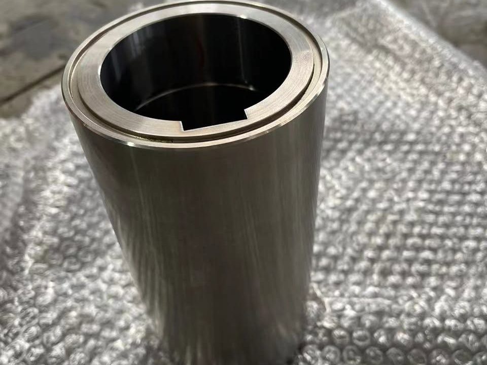
The shaft sleeve covers the shaft where the seal or the packing runs. Wear, fretting and corrosion in that area then fall on a part that can be renewed, not on the shaft itself. Some pumps use a solid shaft without a sleeve instead, which keeps the shaft stiffer at the seal faces, and a cartridge seal carries its own sleeve, so a pump fitted with one may have no separate shaft sleeve. Sleeves are made in stainless steel or a higher alloy to suit the liquid.
Power end: shaft, bearings and bearing frame
The power end carries the rotor and keeps it where the wet end needs it. On an overhung pump the impeller hangs beyond the bearings, so the stiffness of the shaft and the radial load on the impeller, which rises as the pump runs away from its best efficiency point, decide how far the shaft deflects at the seal faces.
Shaft
The shaft carries the impeller at one end and the coupling hub at the other, and transmits the full torque of the motor. It is usually carbon or alloy steel such as SAE 4140, or stainless steel where the liquid can reach it. It is replaced when it is bent, when its bearing or impeller fits are worn, or when it is cracked.
Radial and thrust bearings
Two bearings share the load. The inboard bearing, nearest the impeller, is the radial bearing, usually a single-row deep-groove ball bearing; it carries radial load only and lets the shaft float axially. The outboard bearing is the thrust bearing: it carries the axial thrust and part of the radial load and fixes the shaft’s axial position. On ASME B73.1 pumps it is usually a double-row angular-contact ball bearing; heavier duties use a matched pair of angular-contact bearings. Bearing failures are more often caused by contaminated or insufficient oil, misalignment or operation far from the best efficiency point than by the bearing itself.
Bearing frame, lubrication and isolators
The bearing frame holds the two bearings in line and forms the oil sump. Most process pumps run their bearings in an oil bath, with a constant-level oiler on the side of the frame topping the sump up to a set level and a sight glass to check it. Some frames use an oil ring or a flinger on the shaft to lift oil to the bearings; larger installations may use oil mist, and some small pumps use grease. Where the shaft leaves the frame, bearing isolators or lip seals keep the oil in and water and dust out. Lip seals rub on the shaft and wear; labyrinth isolators have no rubbing contact.
The frame adapter joins the bearing frame to the casing and centres the rotor in the casing bore. Bearing frames come in a few sizes; the power frame cross-reference lists them.
Coupling, baseplate and driver
The coupling connects the motor shaft to the pump shaft. A flexible coupling transmits the torque while taking up small misalignment and axial movement, but it does not replace accurate alignment: a misaligned coupling loads the bearings and the seal. On process pumps the coupling usually has a spacer, a removable centre section that leaves a gap between the two shafts, so that the back pull-out assembly can be removed without moving the motor. A guard covers the coupling while the pump runs.
The baseplate holds pump and motor in alignment and is usually grouted to the foundation. The driver is usually an electric motor, sized with a margin over the pump’s rated power that often covers the end of its curve; steam turbines and engines drive some pumps.
How the parts come apart: back pull-out construction
ASME B73.1 and ISO 2858 process pumps are built so that the casing stays in the pipework. With the casing drained, the seal piping disconnected, the coupling spacer removed and the frame foot unbolted, the casing bolts are taken out and the back pull-out assembly is withdrawn from the rear: frame adapter, casing cover, seal, impeller, shaft, sleeve, bearings and bearing frame. The casing stays on its feet on the baseplate with the suction and discharge piping still connected. The seal, the bearings and the impeller can then be serviced on the bench, or a spare assembly can go in to keep the pump running. The what is an ANSI pump guide and the ASME B73.1 explainer cover the construction in more detail.
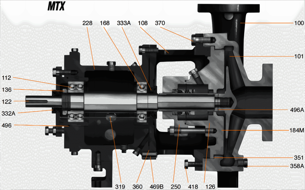
On a sectional drawing each part carries an item number, and that number is what identifies the part in a parts list. Part names and item positions for YSM’s G196 and D Mark III programmes are on the aftermarket ANSI pump parts page, and the item numbers are also published as an open dataset: doi.org/10.5281/zenodo.22920668.
Wear parts and spare parts: what normally gets replaced
Most of a centrifugal pump is structural. The casing, the cover, the bearing frame, the frame adapter and the baseplate normally last as long as the pump and are replaced only after damage: cracks, corrosion, wall loss or worn fits. The parts below wear in normal service, and they make up the usual spare parts list. At an overhaul the shaft is also checked for runout and the bearing fits for wear, against the limits in the pump’s instructions.
| Part | How it wears | What you notice |
|---|---|---|
| Mechanical seal | Face wear, heat checking and chipped faces; elastomers harden, swell or are attacked by the liquid | Visible leakage or vapour at the gland; a rising flush temperature |
| Packing | Hardens and loses volume as it wears against the sleeve | Leakage that keeps increasing after the gland is adjusted; a hot gland |
| Shaft sleeve | Scoring and fretting under the packing or the seal | Leakage that returns soon after new packing or a new seal |
| Impeller | Erosion by solids, cavitation pitting near the vane inlet, corrosion | Lower head and flow; vibration from lost balance |
| Wear rings | The running clearance opens as the rings wear | Lower head and efficiency from internal recirculation |
| Bearings | Fatigue, contamination of the oil, lack of lubrication, misalignment | Noise, heat and rising vibration at the frame |
| Lip seals and isolators | Lip seals wear against the shaft; any seal can be damaged in fitting | Oil loss from the frame; water in the oil |
| Gaskets and O-rings | Take a permanent set in service; chemical attack | Leakage at a joint; they are renewed whenever the joint is opened |
| Coupling element | Fatigue and wear of the flexible element, faster with misalignment | Vibration and noise at the coupling |
A part that fails again soon after it was renewed usually points to the operating conditions, not to the part: running far from the best efficiency point, too little NPSH margin, misalignment or poor lubrication. The NPSH and cavitation guide and the repair or replace guide help separate the two.
How YSM makes these parts
YSM manufactures ASME B73.1 process pumps and their parts at its own 3,000 m² site in Zibo, Shandong, in operation since 2010. The castings and forgings are made in house, with no outsourced foundry work, and machining runs from conventional lathes to gantry machining centres. For the G196 series, all the cast and machined wet-end and power-end parts are made on site: casing, impeller, cover, adapter, frame, bearing housing, shaft, sleeve and feet. Bearings, mechanical seals and motors are bought in: SKF or equivalent bearings, John Crane or equivalent seals and WEG or equivalent motors.
Every impeller is dynamically balanced, pressure-containing parts are hydrostatically tested, the material of casings, impellers, covers and shafts is checked by spectrometer against the ordered grade, and interface and fit dimensions are measured on a coordinate measuring machine. Complete pumps are performance tested on the factory test benches. The factory review lists the equipment; the quality page lists the inspection and test records, which are supplied on request. For parts with no drawing, the reverse engineering route works from a sample or, for simple parts such as sleeves and wear rings, from measured dimensions.

Centrifugal pump parts FAQ
What are the main parts of a centrifugal pump?
The casing (usually a volute), the impeller that spins inside it, the casing cover, the shaft seal (a mechanical seal or packing) with its shaft sleeve, the shaft, the radial and thrust bearings, the bearing frame, and the coupling that joins the pump to its motor on a common baseplate. Closed-impeller pumps also have wear rings.
What are the three main parts of a pump?
The impeller, which adds energy to the liquid; the casing, which contains the liquid and turns its speed into pressure; and the shaft assembly (shaft, bearings and shaft seal), which transmits the power of the driver and keeps the liquid in. On an installed process pump the same parts are grouped as the wet end, the seal area and the power end.
What is the rotating part of a centrifugal pump called?
The impeller. It is mounted on the shaft, and together with the shaft, the shaft sleeve, the rotating parts of the seal, the bearing inner rings and the coupling hub it forms the rotor, also called the rotating assembly.
What are the common spare parts for a centrifugal pump?
The mechanical seal or a set of packing, the shaft sleeve, the bearings, the gaskets and O-rings, and the impeller. Closed-impeller pumps add wear rings, and many plants also keep a coupling element and bearing isolators or lip seals. For critical services a complete spare back pull-out assembly is often kept. The casing and the bearing frame are structural parts and are replaced only when damaged.
What is the difference between a volute and a diffuser?
Both collect the liquid leaving the impeller and turn its speed into pressure. A volute is a spiral passage, single or double, that widens towards the discharge. A diffuser surrounds the impeller with a ring of fixed guide vanes. Most single-stage pumps use a volute; ring-section multistage pumps and vertical turbine bowls usually use diffusers.
What is the difference between a seal chamber and a stuffing box?
A stuffing box is a bore sized for rings of packing, often with a lantern ring, and a gland. A seal chamber is a bore designed for a mechanical seal, usually with more radial space around the seal so that the faces run cooler and cleaner. On end-suction pumps both are usually formed in the casing cover; on split case pumps they are cast in the casing.
Does every centrifugal pump have wear rings?
No. Wear rings are used with closed impellers, where the neck of the impeller runs inside a ring in the casing. Open and semi-open impellers, used in most ASME B73.1 chemical process pumps, run with their clearance at the vane edges instead and have no wear rings.
What does a shaft sleeve do?
It covers the shaft where the seal or the packing runs, so that wear and corrosion in that area fall on a part that can be renewed instead of on the shaft. Some pumps use a solid shaft without a sleeve, which keeps the shaft stiffer at the seal, and a cartridge seal carries its own sleeve.
What is a common problem in a centrifugal pump?
Cavitation, seal leakage and bearing failure are the most common. Cavitation happens when the NPSH available leaves too little margin over the NPSH the pump requires: vapour bubbles form at the impeller eye and collapse as the pressure rises, causing noise, vibration, lost head and pitted vanes. Seal and bearing failures often trace back to misalignment, running far from the best efficiency point or poor lubrication.
Related reading
- What is an ANSI pump? — the end-suction process pump in detail.
- API 610 pump types — overhung, between-bearings and vertically suspended layouts.
- Mechanical seals for process pumps — arrangements, chambers and faces.
- Cast alloys for process pumps — the cast grades used for casings, impellers and covers.
- NPSH and cavitation — why impellers pit and how to prevent it.